1. Main diagrams:
Behavioral Diagram
- Activity Diagram
- Use Case Diagram
- Timing Diagram
- State Machine Diagram
- Communication Diagram
- Sequence Diagram
Structural Diagram
- Class Diagram
- Object Diagram
- Component Diagram
- Composite Structure Diagram
- Deployment Diagram
- Package Diagram
- Profile Diagram
2. Some important diagrams:
Activity Diagram
It is generally used to describe the flow of different activities and actions. These can be both sequential and in parallel. It is used to:
- Model workflows between/within use cases
- Model complex workflows in operations on objects
- Model in detail complex activities in a high level activity Diagram
- Open the word processing package.
- Create a file.
- Save the file under a unique name within its directory.
- Type the document.
- If graphics are necessary, open the graphics package, create the graphics, and paste the graphics into the document.
- If a spreadsheet is necessary, open the spreadsheet package, create the spreadsheet, and paste the spreadsheet into the document.
- Save the file.
- Print a hard copy of the document.
- Exit the word processing package.

- An applicant wants to enroll in the university.
- The applicant hands a filled out copy of Enrollment Form.
- The registrar inspects the forms.
- The registrar determines that the forms have been filled out properly.
- The registrar informs student to attend in university overview presentation.
- The registrar helps the student to enroll in seminars
- The registrar asks the student to pay for the initial tuition.

Use Case Diagram
A cornerstone part of the system is the functional requirements that the system fulfills. Use Case diagrams are used to analyze the system’s high-level requirements. These requirements are expressed through different use cases. We notice three main components of this UML diagram:
Functional requirements – represented as use cases; a verb describing an action
Actors – they interact with the system; an actor can be a human being, an organization or an internal or external application
Relationships between actors and use cases – represented using straight arrows
Dependencies
A number of dependency types between use cases are defined in UML. In particular, <<extend>> and <<include>>.
- <<extend>> is used to include optional behavior from an extending use case in an extended use case.
- <<include>> is used to include common behavior from an included use case into a base use case in order to support re-use of common behavior.
The example below depicts the use case UML diagram for an inventory management system. In this case, we have the owner, the supplier, the manager, the inventory clerk and the inventory inspector.


We are not interested in how the objects interact or change each other, but rather we want to represent how objects and actors act along a linear time axis.
The main components of a timing diagram are:
- Lifeline – a line forming steps since the individual participant transits from one stage to another.
- State timeline – a single lifeline can go through different states within a pipeline
- Duration constraint – a time interval constraint that represents the duration of necessary for a constraint to be fulfilled
- Time constraint – a time interval constraint during which something needs to be fulfilled by the participant
- Destruction occurrence – a message occurrence that destroys the individual participant and depicts the end of that participant’s lifeline


Statecharts find usage mainly in forward and reverse engineering of different systems.
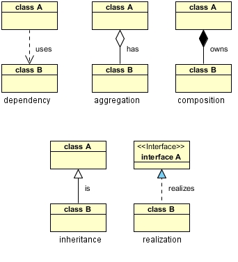
Class Diagram
Class UML diagram is the most common diagram type for software documentation. Since most software being created nowadays is still based on the Object-Oriented Programming paradigm, using class diagrams to document the software turns out to be a common-sense solution. This happens because OOP is based on classes and the relations between them.
Class diagrams contain classes, alongside with their attributes (also referred to as data fields) and their behaviors (also referred to as member functions).

The ‘Checkings Account' class and the ‘Savings Account' class both inherit from the more general class, ‘Account'.
Object Diagram
Object diagrams help software developers check whether the generic abstract structure that they have created (class diagram), represents a viable structure when put into practice, i.e: when the objects of a class are instantiated. Some developers see it as a secondary level of accuracy checking.

Component Diagram
Component Diagram describes the organization and wiring of the components in a system.
Component diagrams help model implementation details and double-check that every aspect of the system's required functions is developed.
The components are less physical and more conceptual stand-alone design elements.
The components provide or require interfaces to interact with other components in the system.
A component is a logical unit block of the system, a slightly higher abstraction than classes.
The Difference Between a Package Diagram and a Component Diagram:
- Package diagram elements are always public, while component diagram elements are private.
- Components are groups of classes that are deployed together and packages are a general grouping device for model elements. Packages can group any model elements, even things like use cases, but in practice they usually group classes, so components and packages tend to be synonymous.
Parts of a component diagram:
Component

A full circle represents an interface created or provided by the component. A semi-circle represents a required interface (input).


Component Diagram for ATM

Package Diagram
It is used to show the organization and relationship of various model elements in the form of packages.
A package is a grouping of related UML elements, such as diagrams, documents, classes, or even other packages.
Parts of Package Diagram:


0 Comments